English
 Vietnamese
 Japanese
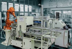
Automatic loading&unloading system for turning machine
Application of automatic loading unloading system for turning machine in automation production
Automatic loading unloading system for lathes as well as automatic workpiece feeding system for milling machines, thread rolling machines, grinding machines, broaching machines, sheet metal working machines … Helping automate the workpiece feeding and taking stages Since then, it has improved manufacturing productivity as well as reduced costs in large-scale production. In the production of automation, embryo supply, scouring, positioning clamping workpieces on jigs, JIG is a very important stage. Therefore, this is the stage that takes up a lot of time in the process of producing a product. In the development trend of modern mechanics, automation of the production process is very important. Understanding this problem, many Vietnamese, Japanese and Indian customers contacted Vietnam to find solutions for automatic workpiece supply for their traditional machining systems. As the system load unloading lathe counter shaft, Camshaft, loading & unloading
Specifications of automatic workpiece feeding system for lathe.
Size: 5641 (L) x 2615 (W) x 3232 (H) (mm).
Operation height of the machine: 1000-1100 mm from the floor.
Main power supply: 3 phase, 200V, 50Hz
Electrical control: DC 24V
Air source requirement: 0.4 - 0.6 Mpa.
Cycle time: Time of lathe machining 28 s / product
-Cycle system = Cycle time lathe + 6s feed level
Number of models and basic sizes of products:
- Model 1: 23411-KZR-6000L = 177.6 mm, Dmax = 28.3 mm
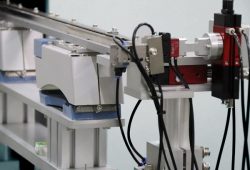
Structure and operating principle of a typical automatic workpiece supply system
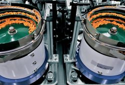
Automatic shaft feeding system for turning lathe includes main clusters:Cluster level input conveyor products
Cluster transfer (cluster 1 and group 2): cluster of products to be put into lathe machine + cluster of hand-held products with automatic robot combination.Intermediate group
Upper and lower cover assemblies
Ouput cluster
Operation sequence of lathe machine feeding system
Below is a description of the general operating principle of the automatic workpiece feeding mechanism. For example, for a model for customers MUSASHI. First workers put the product into the Input conveyor. The number of products placed on the conveyor belt is designed depending on customer requirements.
Transfer cluster 1 picks up the product from Input Conveyor to Standby 1 lathe position.
At the same time, transfer 2 picks up the product from the intermediate assembly into Lathe No. 2.
When Lathe 1 and Lathe 2 are convenient, the gripper on the Transfer cluster 1 takes down the convenient product, then places the workpiece.
At the same time, the gripper on Transfer Group 2 also picks up the product from Lathe 2 and places the new workpiece.
The gripper on Cluster Transfer 1 carries the product into the intermediate assembly. The gripper on Cluster Transfer 2 carries the product into the Jig at the lathe.The cycle is repeated for the next product.
Outstanding feature of automatic loading unloading system for lathe
The advantage of an automatic feeding system is that it can replace people in one or more production stages. Among them, the work of supplying embryos and jigs is attached to the jigs on the machine. And removing the product from the machine after processing is the most feasible automation steps to reduce cycle time.
Automatic workpiece provides economic efficiency in mass production with similar or similar parts. Changing the solution of automatic workpiece provisioning for each predetermined product is quite simple with jig replacement, quick dandory. The time of embryo feeding and taking products of the system is very short, only about 6s helps increase the productivity for machine tools. The above time, with one or several single production products is negligible. However, try to multiply the product batch by several tens of thousands of parts per month. Or simply mass production on a machine. You will clearly see the absolute productivity and benefits of the automated system.
Instruction on operation and dandory Always follow the operating procedures in the CNC document provided for each machine, including: Initialize the system (turn on the circuit breaker in turn, supply electricity to the machine)
Operating in manual mode according to the instructions: switch to manual mode. Control cylinders, motors, robots operating on HMI screens. Switch the device to the original with return ... Notice always check lathe condition before running: Resist center to root / Open chuck / Main door closed / Select Auto mode.
Notice when the machine reports an error:
Operate in automatic mode with the way to bring the machine to automatic mode and operate the machine. Note: When you first switch to Auto mode, the lathe does not give feedback signal to the Loader system, the Loader will pick up the product and stand above the lathe waiting for the signal. To click run, click on the "CONVENIENT 1 READY" button (with Loader1), "CONVENIENT 2 READY" (with Loader 2) until the Loader starts moving down inside the machine.
When an error occurs, the system stops immediately, the STOP lamp is lit, the START light is off, then we have to check the display errors. Proceed to fix the error then press the RESET button to clear the error, then the STOP light stays on. Hold down START for 2 seconds to continue the cycle.
For example: A defective cylinder stuck in the cylinder's clamping state. After resetting the cylinder, the journey progress, press Reset to clear the error. T
hen hold START for 2 seconds to continue. The case of a cylinder error cannot fix the error according to the way usually required to adjust the parts in manual control mode or switch Switch to MANUAL and return the device and run again.
If an error occurs, the robot needs to power off, restart and check the cause
Robot is faulty, overloaded. Then Return returns.
Note when maintaining and maintaining automatic workpiece supply system:Always check and maintain weekly and monthly for structures and equipment. Includes: engine, cylinder, guide silver, bearing bearings. Chain structure, conveyor belt, clamp arm, transfer cluster and slide. Power system, electrical cabinet, sensor, ...

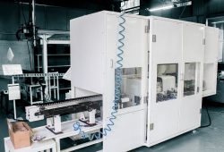
Image: application of automatic feeding system for broaching machines.
The system has been successfully integrated by CNCVina and commercial production has been exported to Indian and Philippine customers since 2015. Automatic loading systems (Loading & Unloading) always bring productivity in production and high profits for businesses. Automated systems and automatic machines can be designed, manufactured and integrated by CNCVina with many different applications such as turning, rolling, tapping, ... If you really want to keep up and Breaking through the 4.0 industrial revolution, find us to get the most reliable companion.